
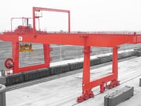

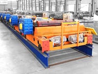
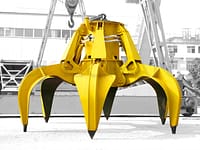
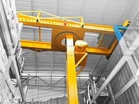


The design is for the trolley part of the crane. The lifting trolley travels laterally along the trolley track, while the hook does the lifting movement. Its working range is the rectangular space of the lot it can travel in, which is exactly in line with the general form of the workshop.
Through the overall design calculation of the trolley running mechanism part and the lifting mechanism part of the overhead crane, as well as the calculation of the motor, coupling, buffer, brake, steel wire rope selection; running mechanism and lifting mechanism of the reducer design calculation and parts of the calibration calculation and structural design, the design of the mechanical part of the two important mechanisms of the trolley of the overhead crane is completed. Through this series of design, to meet the lifting capacity of 50/10T requirements, and trolley running and lifting mechanism structure is simple, easy to disassemble, easy maintenance.
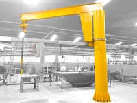
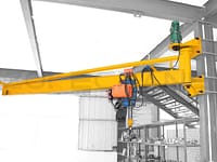
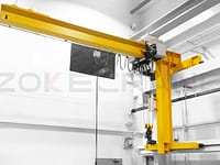
Overall design of the crane trolley
The overhead crane trolley is mainly composed of three major parts: the lifting mechanism, the trolley running mechanism and the trolley frame, in addition to a number of safety protection devices.
Design of trolley running mechanism
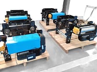
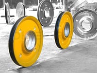
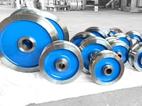
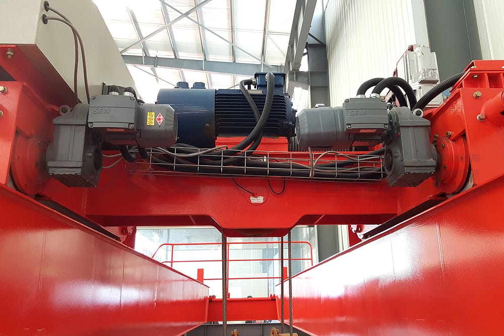
In a medium tonnage overhead travelling crane, the trolley has four travelling wheels. When laying out the individual components of the lifting mechanism, the total centre of gravity of the mechanism should be close to the longitudinal centreline of the trolley frame so that a more uniform wheel pressure can be achieved. The wheels and bearings form a unit assembly (wheels with angular bearing box), which is placed underneath the trolley frame so that it can be easily loaded and unloaded at height. By using a vertical gearbox, the motor and brake can be placed on top of the trolley frame, making it easier to carry out installation and maintenance work and reducing the flat size of the trolley frame, making it compact.
A widely used form of trolley running mechanism in which the reducer is placed in the middle of the two trolley wheels so that the drive shaft on each side transmits only half of the total torque. The drive is carried by means of a half-tooth coupling and an intermediate floating shaft (the two floating shafts can be of equal length or one long and one short). It is also possible to place the vertical gearbox close to one wheel and connect it directly to the wheel with a safety-tooth coupling (only one section of the floating shaft is used). It is easy to install and also has a better floating effect. Considering the influence of the deformation of the trolley frame, a section of floating axle is also added on occasions where the trolley gauge is large, in order to improve its compensation effect.
Lifting mechanism design
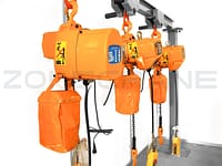
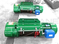
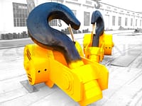
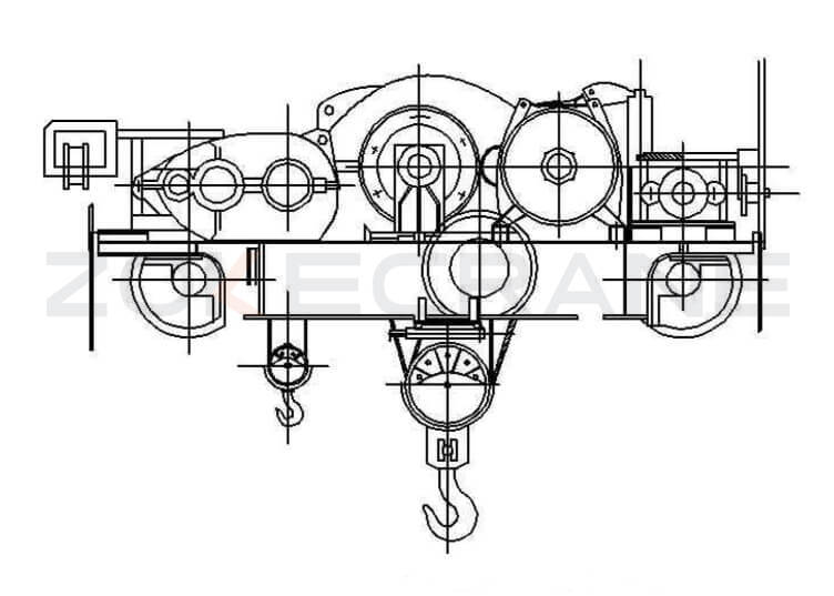
The lifting mechanism consists of an electric motor, transmission device, drum, brake, pulley set and hook device.
Due to the different structure and combination of these parts, there can be a variety of structural forms, but regardless of that form, should be taken into account to improve the force of the parts, reduce the size and weight, safety and reliability, smooth work, easy assembly and maintenance and other factors.
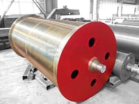
Overhead crane pulley sets are generally double pulley sets, the corresponding drum is also left and right symmetrical double spiral groove of the volume Jane, or ordinary double drum.
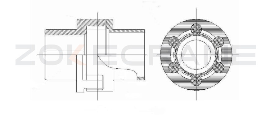
As a result of manufacturing and installation errors and frame deformation after loading, so that the transmission parts between the axis is easy to produce eccentricity and skew, so the bridge crane should be used on the elastic coupling, the past has been using the tooth coupling, compensation effect is good, just complex processing, wear and tear. Now the bridge crane, using plum-shaped flexible coupling, the following figure coupling by the left and right claw-shaped disk and the middle core. Core with polyurethane material pressed into plum-shaped, according to the diameter of different, divided into six, eight, ten petals, a better elastic deformation capacity, use it to transmit power, can reduce the impact and make up for the shaft deflection and different center, the effect is better. This kind of coupling has simple structure, large compensation, impact resistance, vibration and wear resistance, no noise, long life, easy to install and maintain, and is a new type of coupling to promote the use.
On overhead cranes, a block brake is generally used, usually mounted on the high-speed shaft of the reducer.
Trolley frame design
The trolley frame is generally made up of welded longitudinal beams and crossbeams of steel plates. The trolley frame has to bear the full lifting weight and the self-weight of each body, and should have sufficient strength and rigidity, while at the same time reducing the self-weight as far as possible to reduce wheel pressure and bridge load. The trolley frame of the crane is now a welded structure, made of steel plates or sections welded together. According to the distribution of forces on the trolley, the trolley frame consists of two longitudinal beams and their connected crossbeams in the direction of the track to form a rigid whole, the two ends of the longitudinal dye left with right-angle cantilever to install the wheel's angular bearing box.
Safety devices
The main safety devices are railings, baffles, limit switches, stoppers and buffers.
Railings and baffles
The railing is used to protect the safety of maintenance personnel during operation. It is set on the edge of the trolley table perpendicular to the trolley track. For the convenience of the trolley maintenance personnel, the other two sides of the trolley are not provided with rails. The railings can be made of angle steel or steel pipe and are not less than 800 mm high.
The barrier plate is mounted on the outside of the wheels of the end beam of the trolley frame and is used to push away any obstacles that may be on the trolley track to facilitate the operation of the trolley.
Limit switches
It is mainly used to limit the limit positions of the hook, trolley and carriage. When these mechanisms operate to their limit positions, they can automatically cut off the power supply to prevent accidents caused by operating errors. A lever type limit switch in the limit switch box outside, extending a short shoulder shaft, in the shoulder fixed with a curved lever, one end of which is heavy hammer 1, the other end a rope hanging another heavy hammer 2 equipped with a ring sleeve 3, this ring sleeve 3 set in the lifting wire rope outside, under normal circumstances do not hinder the movement of the wire. As the moment of the heavy hammer 2 is greater than the moment generated by the heavy hammer 1, the curved lever turns clockwise to the limit position. However, when the hook rises to the highest limit position, the battering ram above the hook hanger lifts the weight 2 and the curved lever rotates counterclockwise by an angle under the action of the weight 1 at the other end, thus separating the electrical contacts of the micro switch in the box and stopping the hook movement to protect the equipment from damage. The limit switches for the trolley movement mechanism are also cantilevered levers, mounted at both ends of the trolley track. When the trolley is driven to the limit position, the lever just presses against the rocker arm of the limit position switch, forcing the rocker arm to rotate, thus cutting off the power supply and ensuring that the trolley brakes in time and does not rush out of the track.B Screw type limit switch The main working parts of the limit switch are the screw and the slider, the screw has a threaded slider on top, and the slider is set on top of the guide crutch. When the screw is driven by the drum to rotate, the slider can only move along the screw to the left and right. When the drum rotates to the equivalent of the highest limit position of the hook, the slider also happens to move to the right end of the limit position to press the electrical switch, so that the power is cut off and the lifting mechanism stops moving. The relative position of the slider on the screw can be adjusted by means of a screw, this limit switch is lighter than the heavy hammer type, as it is installed on the end of the drum on the trolley frame, so the assembly and adjustment are very convenient, and is now widely used.
Retaining irons and buffers
In order to prevent limit switch failure, spring-loaded buffers and stop irons are fitted at the two extremes of the large carriage frame track, using the second to stop the trolley from advancing and to absorb the function of the trolley on impact. The buffers are placed on the trolley frame and can also be cushioned with wooden boards or rubber blocks when the trolley is not moving at high speed.