


- 21 Years Manufacturer Experience
- Competitive Price
- OEM and ODM Accepted
- Mass Production, Inventory
Drawing Provided
Price Provided
Standard Production Finished
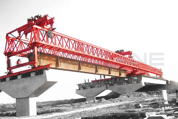
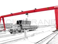
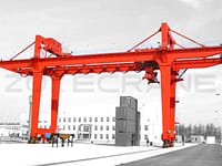
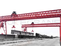
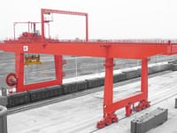
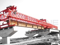
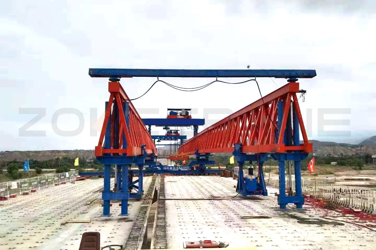
Concrete Beam Launcher
- Below details needs to be provided to quote the price:
- The max. Weight of concrete beam: 50,80,100,120,140,160,200,250T
- Span: 20,25,30,35,40,45,50M
- Lift height: 10M
- Max. cross slope of bridge: 3%
- Max. Longitudinal slope of bridge: 3%
- Min. Curve radius of bridge: 250/350/400/500M
- Angle of skew bridge: ≤45°
- Application: Highway bridge/railway bridge
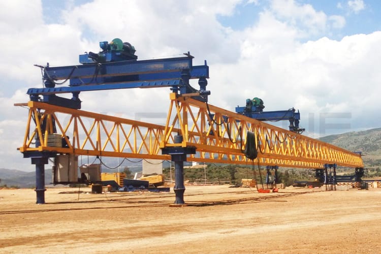
Introduction
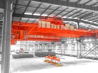
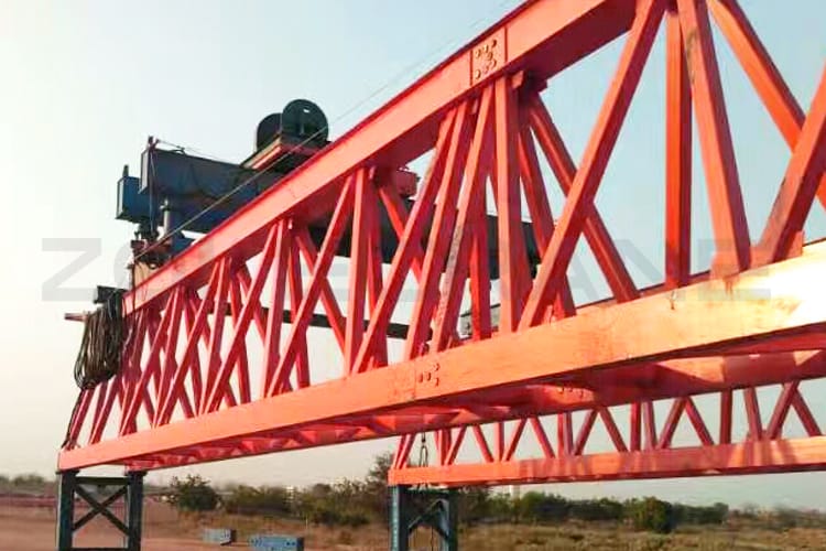
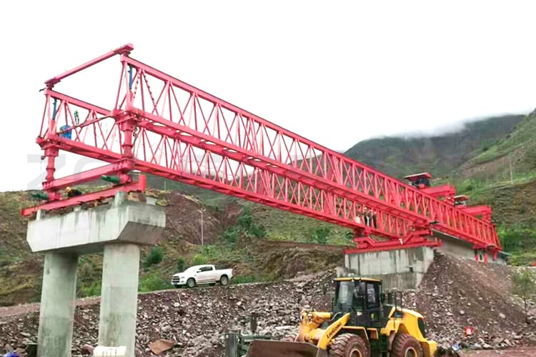
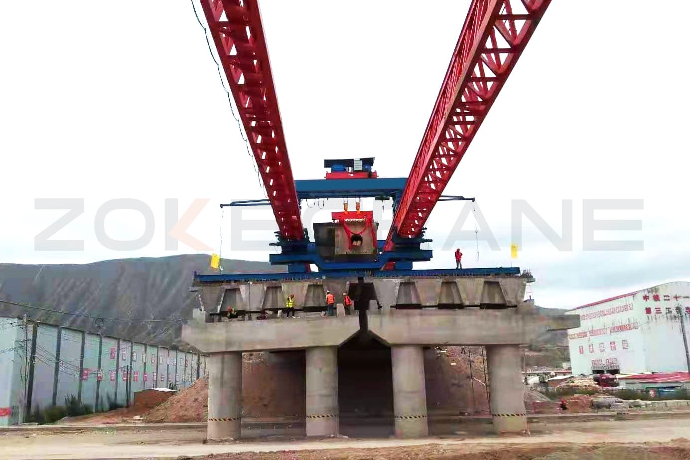
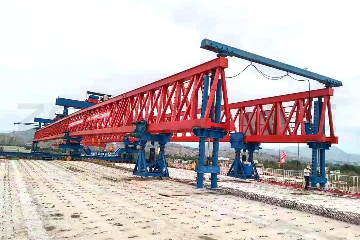
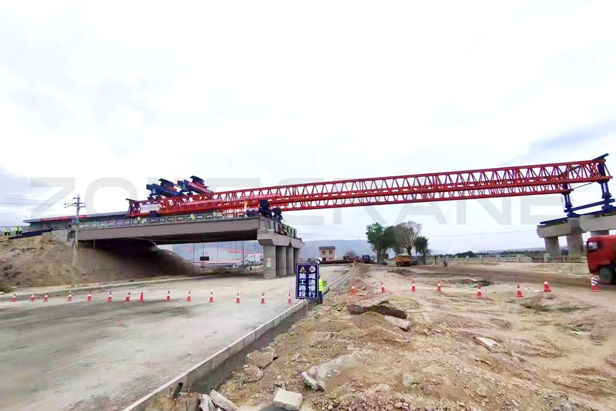
Truss type double girder beam launcher is a special machine for putting precast concrete beam on the bridge pier, it is also one of the most important machine used in the road construction.
Designed for precast beam assembly without crane assistance the beam launcher is perfectly suited for bridges and viaducts with high piers and difficult ground access situations, or when constructing over water and areas with poor soil conditions.
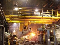
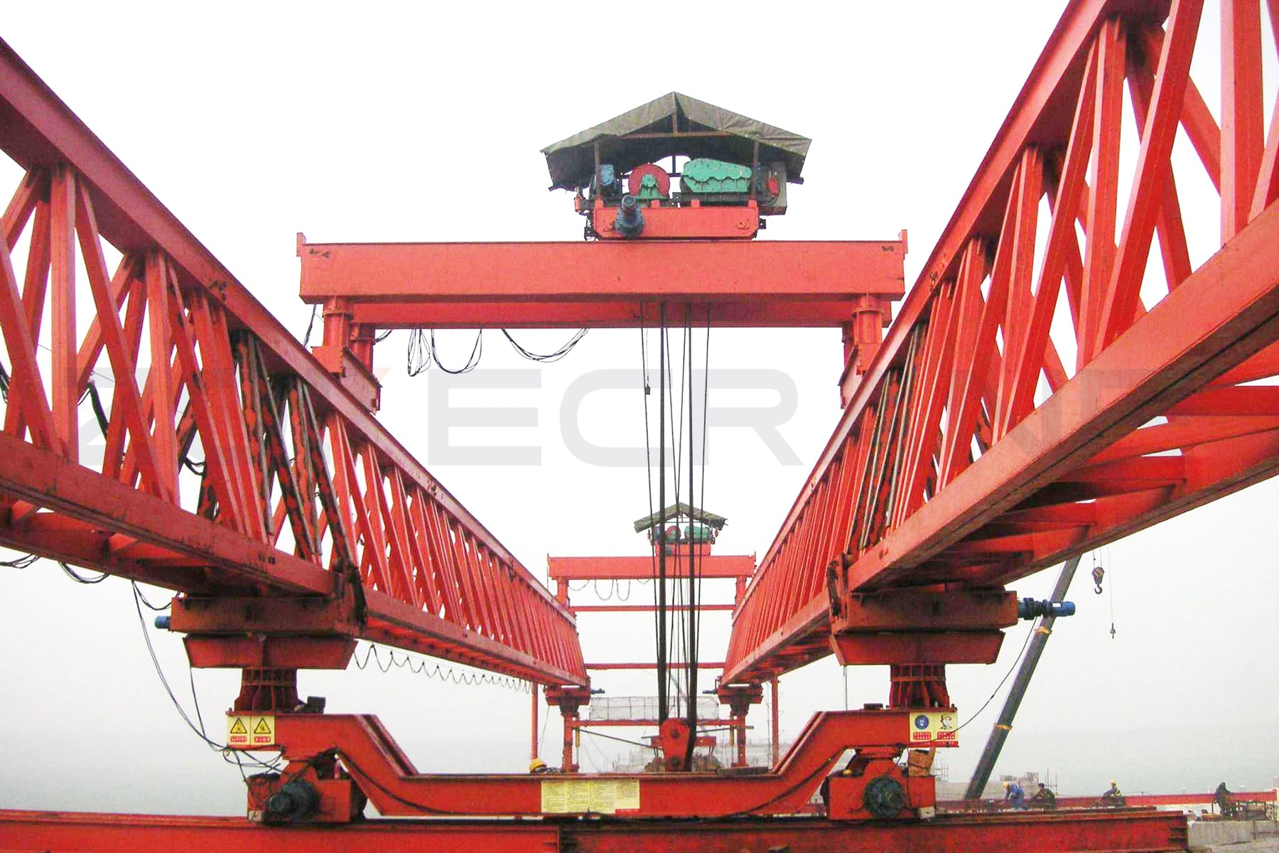
Beam launcher belongs to overhead crane, but is different from the ordinary overhead crane, its work condition is very bad, the worker must have the very high operating skill and safety awareness.
This machine can be not only used in highway bridge, but also rail way bridge.
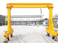
Advantages
- High utilization rate of storage yard
- Relatively simple mechanical structure
- Powered by electricity, it saves energy and reduces pollution
- Main parts are from international top brand, like SEW, ABB, SIEMENS, SCHNEIDER and so on
- Automatic operating system, and greatly increase production efficiency.
Main Parameters
| Span(m)/capacity(t) | 25/60 | 30/80 | 30/120 | 40/140 | 40/180 | 50/200 |
|---|---|---|---|---|---|---|
| Lifting speed(m/min) | 0.95 | 0.9 | 0.65 | 0.56 | 0.5 | 0.45 |
| CT speed(m/min) | 3.3 | |||||
| LT speed(m/min) | 3.3 | |||||
| CT speed(m/min) | 3.3 | |||||
| LT speed(m/min) | 3.3 | |||||
| Bridge curved radius(m) | ≥200 | ≥250 | ≥250 | ≥350 | ≥350 | ≥500 |
| Angle of skewing bridge | ≤45° | |||||
| Max. cross slope | ≤3% | |||||
| Max. longitudinal slope | ≤3% | |||||
| Work duty | A3 | |||||
| Power supply | 3AC 220~480V 50/60Hz | |||||
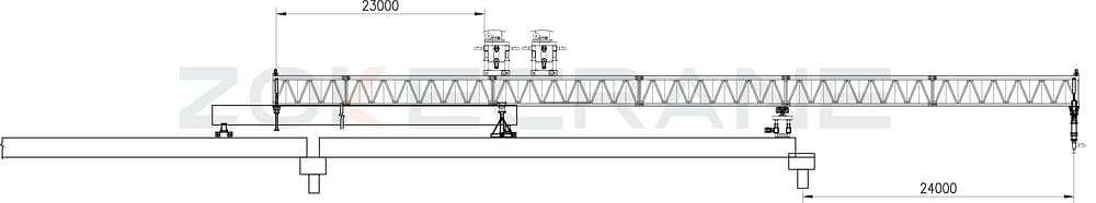
Working Principle
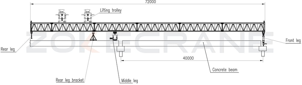
- Installthe launcher,check the functioning of the institutions, subject to normal after the main girder leveling.
- Move rear leg bracket and middle leg to the place like above drawing shows.
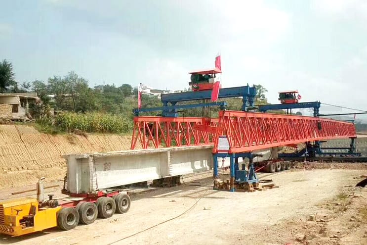
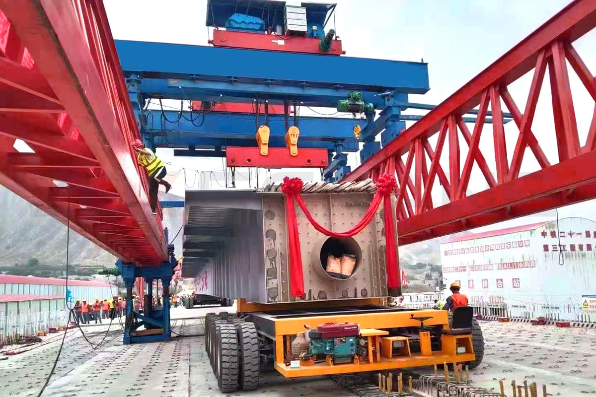
- Place concrete beam to the end of launcher;
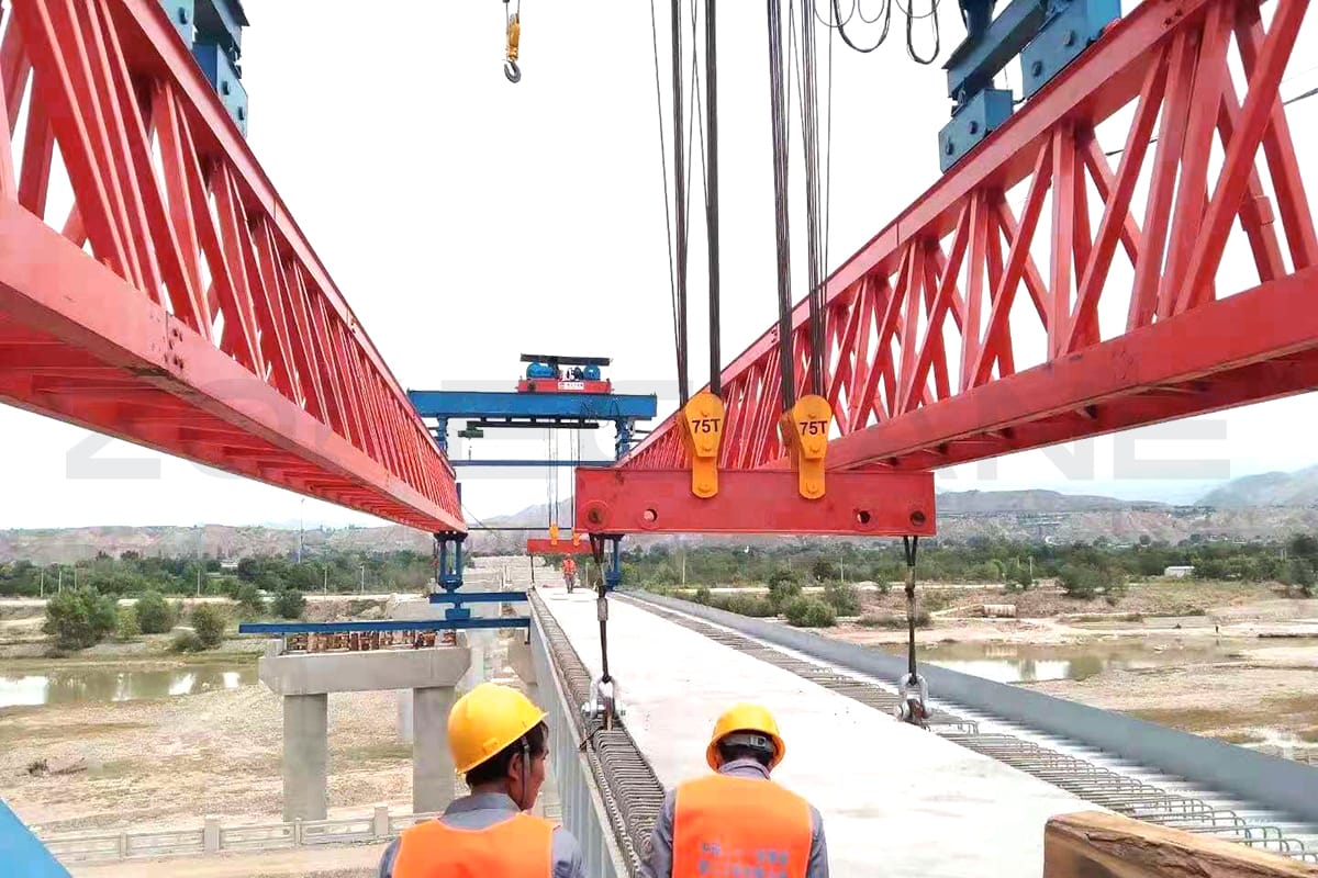
- Start hydraulic system of front leg and hydraulic system of rear leg bracket, to lift the main girder of launcher to suitableposition, then put load bearing pin (Abbre. 'pin' ) and loose the hydraulic system to make the main girder steady.
- Lift middle leg with rail track for tranverse moving and move 40m on suitable position of front bridge abutment by front lifting trolley, and then put down the middle leg and rail track.
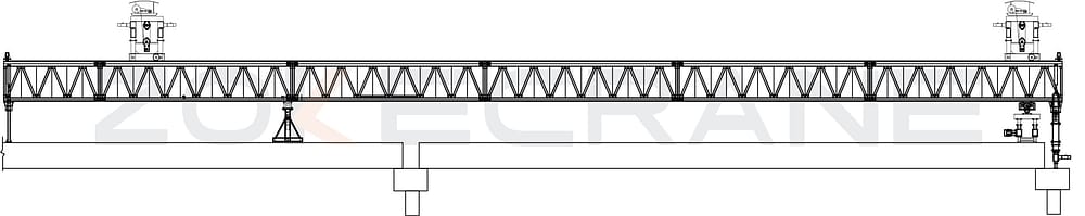
- Start hydraulic system of front leg and hydraulic sytem of rear leg to lifting main girder to suitable position to make rear leg bracket free of burden, and put in pin of the rear leg hydraulic and the front one's, and then loose hydraulic of the two legs.
- Loose the hydraulic system of bracket and pull out its pin.
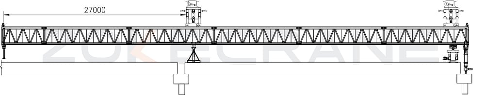
- Move the rear lifting trolley over the bracket and take it the 27m position from rear end of main girder(see the drawing above), and then put it down on.
- Start hydraulic system of front leg and hydraulic system of rear leg again and put out their pins, and then loose the hydraulic systems, to make all the burden on reverse wheel of bracket and middle leg.
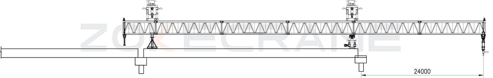
Start reverse wheel of bracket and reverse wheel of middle leg, to move the main girder 24m, Meanwhile, start front lifting trolley and rear one, move the same 24m rear.(see theirposition on above drawing)
- Start hydraulic system of rear leg to make middle leg off the ground of bridge, then movebracket to 23m position from rear end of girder by rear lifting trolley.
- Loose hydraulic system of rear leg.
- Move front lifting trolley next to rear lifting trolley.
- Move girder transportation trolley with girder to rear position.(as drawing shows), and thentie the girder to slings of rear lifting trolley and tighten wire rope.
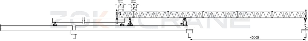
- Start reverse wheel of middle leg and bracket, as well as the lifting trolleys, make themain girder move front 21m onto suitable position of new bridge abutment.
- Put and adjust the rail track of front leg for tranverse moving, make sure the rail parallel with the rail of middle leg.
- Adjust front leg height and put the pin in, to make front on right condition for launching.
- Loose rear leg and the bracket off the bridge, and cross move the launching crane to right to start launch girders.
Need Help? Contact our support team today !
If you have any questions or free quotes for the product, we will reply within 24 hours! please do not hesitate.