
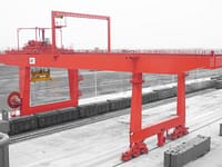


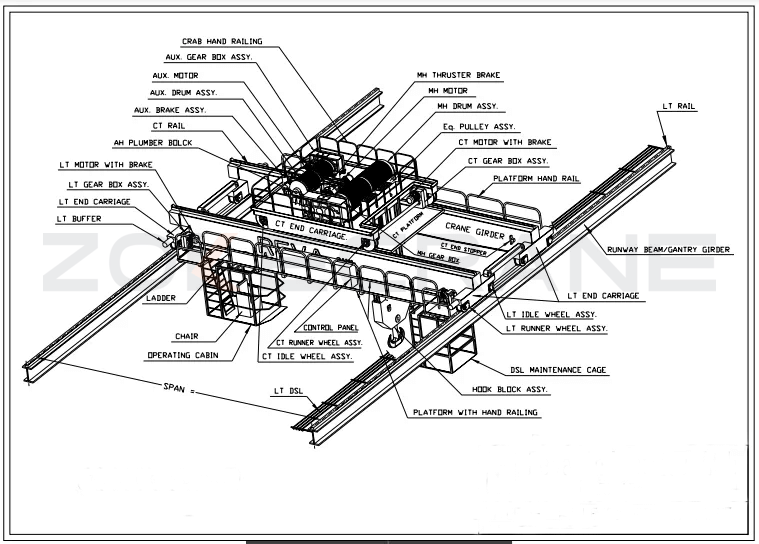
Overview of the gantry crane lifting mechanism part
- Mainly includes the upper and lower trolley lifting and running mechanism, large car running mechanism and maintenance cranes, elevators and other auxiliary institutions. The design of each institution should conform to the specification and meet the requirements of its working level.
- The equipment and components of each institution, such as gearboxes, brakes, couplings, reels, go wheels, pulleys, hooks, bearings and the materials used must be selected and strictly calculated and calibrated in accordance with the relevant norms and standards. In order to reduce the number of specifications of spare parts, the design should try to use common, easy to procure the product.
- Set up a centralized lubrication system according to the institution, the lubrication point should be convenient. Easy to check the lubrication status, the lubricant used for the use of the environment (in -20 ℃ can be used normally). To have lubrication point chart, lubrication point location is clear.
- Walking mechanism using motor, reducer, brake "three in one" combination form, through the dolly centralized drive mode. Bearing in principle using rolling bearings, gears and walking mechanism to go wheel working surface must be surface hardening treatment in line with the specification requirements.
- The trolley lifting mechanism and trolley, trolley walking mechanism should be installed absolute value encoder, to provide accurate signals for the electronic control system to indicate its current position.
- The trolley machine room should take measures such as heat insulation, heat preservation, dustproof and rainproof.
- lifting mechanism wire rope should be used without distortion, no stress, no loose tendency of 8 strands of steel wire rope, the outer strand surface solid, wear-resistant and lubrication to make the steel core long-lasting rust-free wire rope. Its nominal tensile strength level should be in line with the corresponding current standard products.
- large car, on, under the trolley walking mechanism are to have broken shaft protector, and easy maintenance.
- The brake of the hoisting mechanism adopts disc brake.
Upper trolley
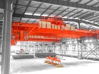
The upper trolley is equipped with two independent groups of 350-ton lifting mechanism, traverse mechanism, trolley running mechanism, trolley frame, machine room and ladder, platform and other institutions and structures. Equipped with safety devices such as stopper, buffer, anti-tipping device, storm-proof anchoring. And set up deceleration, stopping and other travel limiters.
The upper trolley stroke should be expanded as far as possible to minimize the operating blind spot. The upper trolley should make full use of the 130m span of the crane to maximize its travel to meet the requirements of the construction process and increase the operating area.
The limit distance of the hook from the centerline of the rigid leg track and the centerline of the flexible leg track is 3m.
Upper trolley hoisting mechanism
- The whole hoisting mechanism is installed in the machine room, and its arrangement should be convenient for personnel maintenance as well as crane parts lifting. The cart travel mechanism should be convenient for disassembly, assembly and overhaul.
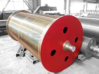
- Using double or multi-layer winding reel, steel rope should be involved or released at the same time and always parallel to stretch roll, to ensure that the operation of the hook is not vertical tolerance control within 5%. Steel rope reel should be designed with rope discharge mechanism, and set the steel wire rope anti-drop safety device.
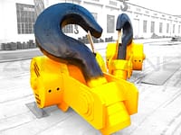
- The two hooks can be single-acting or linked. Set the height indicator and travel limiter, and control the error within 100mm when lifting and descending at the same time, and issue alarm signal when exceeding the difference.
- The weight difference and distance difference between two hooks should be equipped with indicator and limiter, the maximum weight difference is 150 tons, and the distance limit tolerance is 100mlm.
Upper trolley traverse mechanism
- The upper trolley two hooks set horizontal traversing mechanism. The single hook can move a distance of 2m but the difference between the two hooks and the center of the trolley is within 200mm.
- The traverse mechanism should be installed with absolute value encoder to provide position signal.
- Through the horizontal screw drive device, the lateral movement of two sets of hooks is realized.
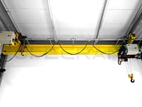
Upper trolley running mechanism
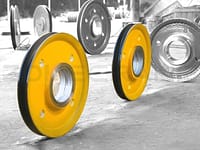
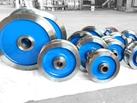
The trolley running mechanism adopts the combination form of motor, reducer and brake, and the wheels can be driven centrally by the cart or independently; the walking wheels of the walking mechanism are made of ZG42CrMo material or rolled wheels with equal performance, and the hardness of the tread surface of the wheel is hardened by induction quenching at a frequency of HB330~380. 380, at a depth of 20mm hardness of not less than HB260.
Lower trolley
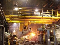
The lower trolley is equipped with a set of independent 350t main hoisting mechanism and a set of 50t sub hoisting mechanism, which consists of hoisting mechanism, trolley running mechanism, trolley frame, machine room and ladder, platform and other institutions and structures. The lower trolley can pass under the upper trolley to complete the aerial turning operation of group block segmentation. Equipped with safety devices such as stop gear, buffer, anti-tipping device, storm-proof anchoring, etc.
The lower trolley stroke should try to expand the moving distance to minimize the blind area of operation. the limit distance of 350 tons main hook from the center line of the track on the rigid leg side is about 7.5 meters, and from the center line of the track on the flexible leg side is about 7.5 meters.
The form of the lower trolley lifting mechanism and running mechanism is basically the same as that of the upper trolley. In consideration of reducing the number of specifications of spare parts, it is as common as possible with the upper trolley.
Lower trolley lifting mechanism
- The whole lifting mechanism is installed in the machine room, and its arrangement should be convenient for personnel maintenance and lifting of crane parts. The cart travel mechanism should be convenient for disassembly, assembly and maintenance.
- the main and vice hoisting mechanism are used double or multi-layer winding reel, steel rope should be involved or released at the same time and always parallel to stretch roll, in order to ensure that the operation of the hook is not vertical tolerance control within 5%. Steel rope reel need to be designed with rope discharge mechanism, and set up anti-drop safety device.
Under the trolley running mechanism
The trolley running mechanism adopts the combination form of motor, reducer and brake, and all the wheels can be driven in a centralized way or in an independent way. The walking wheels of the traveling mechanism are made of ZG42CrNo material or rolled wheels with the same performance, and the hardness of the tread surface of the wheels is HB330~380 by induction quenching, and the hardness is not less than HB260 at a depth of 20mm.
Cart
The cart is composed of rigid leg side running mechanism and flexible leg side running mechanism. It is equipped with a series of equipment such as windproof rail clamp, anchoring device, deflection correction device, rail cleaner, buffer, stop device, sound and light alarm, emergency stop button, etc. Adopt balanced dolly way, the dolly are connected by pin to ensure that the load makes wheel pressure evenly through the balancing system. The trolley should be equipped with decelerator and travel limiter, which will automatically decelerate when the trolley runs close to the end point of the track and automatically stop when it reaches the minimum safety distance.
The running mechanism of the cart adopts the combination form of motor, reducer and brake, and the last level of transmission adopts open gear transmission. The walking wheels of the traveling mechanism are made of ZG42CrMo material or rolled wheels with the same performance, and the hardness of the tread surface of the wheels is HB330~380 by induction quenching, and the hardness is not less than HB260 at a depth of 20mm.
The cart running mechanism should have wheel breakage protection device; the balance beam should have support points to facilitate wheel and frame disassembly and maintenance.
Clamp rail: in the rigid, flexible leg on each side of the bottom of the lower beam with each articulated self-locking clamp rail, in any case (such as power failure) with automatic clamping and safety open function, and can be manually operated.
Large car correction system
The cart operation adopts double-protection deflection-correcting device. Through the absolute value deflector installed on the standard wheel of the rigid and flexible leg side and the calibration of the reference magnetic block fixed on the track foundation, the actual position signal of the two legs is detected and input to PLC for comparison and operation, and the speed of the flexible leg is adjusted to realize the synchronous operation of the car. In addition, at the connection between the flexible leg and the main beam (the position can be easily adjusted), there is a corner protection sensing device. When the skew deviation value reaches 3% of the crane span (390mm), the travel mechanism will stop in an emergency and make manual correction to eliminate the deviation and then resume the operation of the crane.
- When the deviation of the rigid and flexible leg running stroke reaches 1%~2% of the crane span. (130mm~260mm), the control system starts to correct the deviation automatically.
- When the deviation of rigid and flexible leg running stroke exceeds 2% and less than 3% of the crane span (260mm~390mm), it automatically enters the state of speed reduction and correction of deviation, and issues relevant warnings.
- When the deviation of rigid and flexible leg running stroke reaches 3% of the crane span (390mm), it will automatically stop for protection and issue alarm signal. After the deviation is eliminated by manually operating the flexible leg to correct the deviation, operation is resumed.
Windproof anchoring, anchoring system: To ensure the safety of the crane in non-working condition, especially in high winds and storms, the design should set up a perfect anchoring device and use anchoring pins to fix the big car in case of storms.
Anchoring device interlocked with the electrical system, the crane can not work when anchored.
When encountering a very large storm (wind speed 40m / s ~ 55m / s), in the rigid, flexible leg side need to be equipped with anchor devices to increase the non-working state of the whole machine's ability to resist overturning, to ensure that the crane is not blown over by the wind.
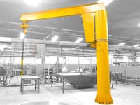
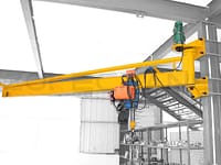
Maintenance crane
- In order to facilitate the maintenance of the upper and lower trolleys and electromechanical equipment, a maintenance crane is set up on the top surface of the main beam end on the rigid leg side of the crane, which is designed with reference to the crane specifications and the corresponding standards. Maintenance crane technical specifications and related parameters are submitted for approval in the preliminary design review.
- The lifting capacity of the maintenance crane should meet the weight of the largest maintenance parts to be lifted in the upper and lower trolley mechanism, its working range to meet the upper and lower trolley drive to the gantry crane under the boom, can serve in the trolley machine room everywhere, its lifting height to meet the upper and lower trolley to be lifted to the ground for maintenance parts.
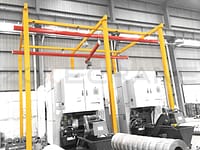
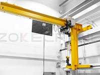
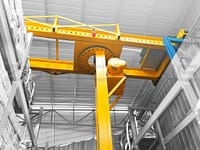
- The maintenance crane is a rotating jib crane, mainly composed of lifting mechanism, rotating mechanism, running mechanism, rotating jib and column. Lifting, running and rotating are manipulated by the button box, the length of the connecting cable should meet the needs of use.
- Should be set up lifting, running limit device, rotating arm automatic locking device, cushioning and stopping device for trolley operation and parking wind swing device.
- The rotation and operation of the maintenance crane is driven by AC frequency conversion motor.
- Maintenance crane lifting mechanism wire rope using no twist, no stress, no rotation, no loose tendency of the wire rope, in line with international and China's current standards of products.
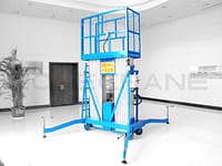
Elevator
- The elevator is installed in the rigid leg, from the bottom of the leg to the top of the leg, according to the structural characteristics of the gantry crane, with a number of layers in the middle to facilitate inspection and maintenance personnel up and down.
- The elevator must be designed and manufactured by professional elevator manufacturers according to relevant standards and certified by relevant departments (including certification by the State Bureau of Quality and Technical Supervision and the Security Bureau). The choice of elevator model must be approved.
- The load capacity of the elevator is 500kg, and it is a dual-use elevator for passengers and cargo. Its normal lifting speed is not less than 1m/s, with smooth acceleration and deceleration and leveling display.
- The elevator shall be equipped with safety protection devices, load limiters, overspeed protectors and emergency protection measures in the event of power failure or electrical fault.
- The speed control drive mode of the elevator shall be frequency conversion speed control drive and PLC program control.
- When the elevator breaks down, there are emergency measures and escape functions to ensure emergency access of personnel.
Lubrication system
The gantry crane is equipped with a centralized lubrication system for each mechanism. The lubrication components are all products of well-known manufacturers.
- Each institution set up centralized lubrication system, centralized lubrication system should be advanced, reasonable, with the use of performance, the location of its lubrication points should be convenient, safe, the lubricants used should be suitable for long-term use under the environmental conditions of the buyer's location. In line with the relevant current standards in China, and convenient to buy.
- Lubrication points should have clear instructions, to have lubrication charts, and fixed in the form of signs in the designated parts.
- Lubrication system and the whole vehicle control system joint control, can realize local, remote control. In the vehicle control system can achieve the lubrication system management, fault display, operation, data statistics and other functions.
- Equipped with portable electric high-pressure oiling pump.
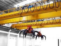
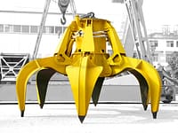
Balance beam type sling (balance beam for short)
Adopt balance beam type sling (with rotation axis, the lower end can reach 90?#65289; in x and y axis direction. The counterbalance beam is a plate welded structure, which is suspended from the hook head of the main hook by the hinge axis. The counterbalance beam sling has sufficient strength and stiffness as required by the specifications. The type of counterbalance beam is determined in the preliminary design review. The hook is set with a metabolic hook head.