
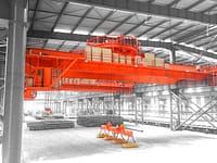


Gantry crane's main use, purpose and basic requirements
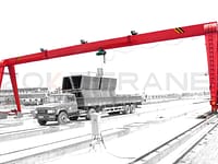
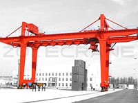
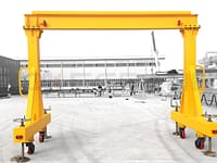
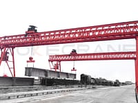
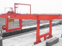
One 450-ton gantry crane, with a gauge of 130 meters and a track length of 350 meters, is installed above the second slide. The crane operation area covers the whole slideway operation area. To improve the speed of group block construction, shorten the time of occupying the slipway, realize the new process of group block construction that the structural deck piece is prefabricated in the workshop, set equipment, pipe sink, electrical instrumentation, bracket accessories, etc. to form a single module, and realize the overall lifting of the single module. At the same time, shoulder the structural deck piece of turning and other large structures loading and unloading.
Gantry crane structure type and function
The gantry crane is composed of the main beam, rigid leg, flexible leg, balance beam, wheel frame and other steel structural parts, the main beam is welded to the rigid leg, and the flexible leg is hinged to connect. The upper trolley with a lifting capacity of 2?50t and the lower trolley of 350t/50t are installed on the main beam, and the lower trolley can pass under the upper trolley. Through the mechanical system and electrical control system such as upper and lower trolley and trolley operation, in order to realize the crane lifting, lifting and air segment turning and other functions. In the whole range of the main beam upper and lower trolley hook centerline overlap when the upper trolley single lift lifting capacity of 450 tons, the maximum lifting capacity of the air turn over 450 tons. The lifting capacity refers to the weight of the lifted object below the sling.
Climatic conditions
Regional climate characteristics: belongs to temperate maritime climate
- Wind: the most wind direction is SE, N, NW, ESE. typhoon every year, 1~2 times a year, the maximum wind speed is 55m/s.
- Precipitation: The maximum annual average rainfall is: 1227.6 mm, the minimum annual average rainfall is 386.3 mm, and the average annual rainfall is 755.6 mm.
- Temperature: temperate maritime climate with no scorching heat in summer and no severe cold in winter. The extreme maximum temperature is 34.4℃, the extreme minimum temperature is -16.0℃, and the annual average temperature is 12.3℃.
- Earthquake: The basic intensity of earthquake is 6 degrees.
- Salt spray: There is salt spray.
- Humidity: annual average relative humidity of 75%.
Design working conditions
- Temperature: maximum temperature +40℃, minimum temperature -20℃.
- Wind speed: gantry crane in the working state of the maximum wind speed of 21m / s (measurement height of 10 meters above the ground), in the non-working state of the maximum wind speed of 40m / s (measurement height of 10 meters above the ground), the maximum wind speed of 55m / s during extreme storms (measurement height of 10 meters above the ground). Should fully consider the changes in wind speed at different heights, and fully adapt to the temperature difference and airflow changes in the location of the client.
- Humidity: maximum relative humidity 92%.
- Fog condition: with mild salt fog, designed at 10 degrees.
- Earthquake: The basic intensity of earthquake is 7 degrees.
Design life
- The design life of the crane is 50 years.
- The life of electrical control system is 15 years.
- Paint life of 15 years.
Design implementation standards and specifications
International standards:
- elated standards of IS0 International Standards Organization
- Related standards of IEC International Electrotechnical Commission
- IEEE International Institute of Electrical and Electronics Engineers standards
- AWS American Welding Society Standard
- JIS Japanese Industrial Standards
- FEM1.001 European Crane Design Code
- AISC American Institute of Steel Construction
- DIN German Industrial Standard
- SIS Swedish Industrial Standard
Chinese standards:
- GB3811–83 crane design specification
- GB6067–85 Safety regulations for cranes
- GB5905-86 crane test specifications and procedures
Main technical performance parameters of the equipment
The composition of the crane
The crane is composed of gantry steel structure, upper trolley, lower trolley, large car running mechanism, maintenance crane, elevator, crane electrical system and other major parts. This crane is also equipped with rail clamps, anchoring devices, anchor devices, wind speed/wind direction meters, deflection correction devices, lifting weight limiting devices, limit devices of each mechanism, equipped with fire alarm and manual non-conductive fire extinguishing devices and various safety protection devices as stipulated in the crane safety regulations.
The design of this gantry crane should pursue: safe operation, advanced design, reasonable structure, convenient operation and maintenance, and its overall technical level reaches the world advanced level.
Performance parameters of the crane
|
Part |
Technical parameter name |
Unit |
Technical parameters |
|
|
Crane |
Upper trolley lifting weight |
t |
450(excluding the weight of the counterbalance beam) |
|
|
Lower trolley lifting weight |
t |
350 |
||
|
Span (big car gauge) |
m |
130 |
||
|
Beam bottom height |
m |
75 |
||
|
Base distance |
m |
Bidder Determination |
||
|
Upper trolley |
Lifting weight of both hooks |
t |
2*350 |
|
|
Allowable maximum deviation of the lifting weight of the two hooks |
t |
150 |
||
|
Lifting height (on rail) |
m |
≥75 |
||
|
Lifting speed |
Full load |
m/min |
0~3.2 |
|
|
Half load |
m/min |
0~6.4 |
||
|
No load |
m/min |
0~8 |
||
|
Symmetrical traverse range of the two hooks of the upper trolley |
m |
13~17 |
||
|
Maximum distance of single hook traverse |
m |
2 |
||
|
The difference between the distance from the two hooks of the upper trolley to the center of the trolley |
mm |
-200~+200 |
||
|
Traversing speed of two hooks |
m/min |
0 |
||
|
Upper trolley running speed (full load) |
m/min |
0~30 |
||
|
No load (wind speed ≤ 15m/s) |
m/min |
0~40 |
||
|
Micro-motion |
m/min |
0~3.5 |
||
|
Cart |
Normal running speed of the cart |
m/min |
0~30 |
|
|
No load (when the wind speed ≤ 15m/s) |
m/min |
0~30 |
||
|
Micro-motion |
m/min |
0~3.5 |
||
|
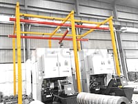
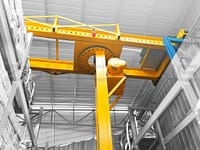
Maintenance crane |
Lifting weight |
t |
Safe lifting of heavy maintenance parts |
|
|
Lifting height (to the rail) |
m |
Meet maintenance needs |
||
|
Lifting range (working radius) |
m |
|||
|
Lifting speed |
m/min |
10 |
||
|
Rotation speed |
rpm |
0.5 |
||
|
Running speed |
m/min |
10 |
||
|
Rotation range |
° |
360 |
||
|
Others |
Large car track type |
|
QU120 |
|
|
Maximum wheel pressure (non-working condition) |
kN |
Bidder Determination |
||
|
Maximum wheel pressure (working state) |
kN |
780 |
||
|
Power supply (main power supply) |
kV/Hz |
AC 10/50 |
||
|
(Standby power supply) |
V/Hz |
AC 380/50 |
||
|
Main power supply method |
|
Cable reel (rigid leg side) |
||
|
Crane main mechanism drive form |
|
AC frequency conversion, stepless speed control |
||
|
The percentage of horizontal force parallel to the crane track when the hook is pulled diagonally |
° |
5%(3°) |
||
|
Percentage of horizontal force perpendicular to the car track when the hook is pulled diagonally (acting on the outside) |
° |
5%(3°) |
||
|
Percentage of horizontal force perpendicular to the big car track when the hook is pulled obliquely (acting between two small cars) |
° |
10%(6°) |
||
Crane working level
|
Part |
Utilization level |
Load state |
Working level |
|
Gantry crane |
U5 |
Q2 |
A5 |
|
Maintenance crane truck |
U2 |
Q2 |
A2 |
Working level of each crane mechanism
|
|
Utilization level |
Load state |
Working level |
|
Main hoisting mechanism |
T5 |
L2 |
M5 |
|
Secondary hoisting mechanism |
T5 |
L2 |
M5 |
|
Small car travel mechanism |
T5 |
L3 |
M6 |
|
Large crane travel mechanism |
T5 |
L3 |
M6 |
|
Maintenance crane hoisting mechanism |
T3 |
L2 |
M3 |
|
Repair of crane trolley travel mechanism |
T3 |
L2 |
M3 |
|
Repair crane rotation mechanism |
T3 |
L2 |
M3 |
Crane basic operation requirements
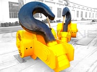
- The upper trolley is equipped with two hooks (I, II hooks) and the lower trolley is equipped with one hook (III hook) and sub hooks, the lower trolley can pass under the upper trolley to realize the turning action of the segment.
- I, II, III hooks can be lifted and lowered separately.
- I+II, I+, II+, I+I+Il synchronized upward opening and diverting.
- The I and II hoisting mechanism of the upper trolley can be operated separately in linkage traverse.
- The upper and lower trolleys operate separately or synchronously.
- The upper and lower trolley lifting mechanism and the large trolley walking mechanism can run simultaneously when no load.
- The travel mechanism of upper and lower trolley and the travel mechanism of large trolley can operate simultaneously.
- The up and down trolley lifting mechanism (three hooks lifting) can run simultaneously with the trolley walking mechanism when the motor load current is less than 50% of its rated current;
- The up and down trolley lifting mechanism and the trolley walking mechanism cannot run simultaneously when the motor load current is more than 50%.
- The joint action of the institutions have interlocking protection function.
- The crane rigid leg side of the walking mechanism and the flexible leg side of the walking mechanism can move together. It can move separately when correcting deflection.
Steel structure of the crane
The main steel structure of the crane includes: gantry steel structure, upper trolley steel structure, lower trolley steel structure, large trolley balance beam and maintenance crane steel structure. The gantry steel structure is mainly composed of main beam, rigid leg, flexible leg and lower cross beam. The rigid legs are rigidly connected with the main beam through welding. The flexible legs are flexibly connected with the main beam through flexible strands. The upper trolley steel structure is mainly composed of upper trolley frame and lifting mechanism, etc. The lower trolley steel structure is mainly composed of lower trolley frame and lifting mechanism, etc. The balance beam of the big car is mainly composed of the cart frame and balance beam at all levels, etc. The steel structure of maintenance crane is mainly composed of tubular column and slewing boom, etc. The technical requirements for the main steel structure are.
- The design of the main load-bearing structure of the crane should strive for simplicity, clear forces, direct load transfer and reduce the impact of stress concentration. Strictly in line with the requirements of static and dynamic rigidity and stability, and should fully consider the impact of the use of the environment on the structure.
- Steel structure using welded structure, the main steel materials should have good welding technology and meet the requirements of low-temperature impact toughness.
- Gantry crane gantry structure design must take into account the convenience and possibility of manufacturing, inspection, transportation, installation and maintenance.
- The manufacture, welding and inspection of the steel structure should be carried out in accordance with the relevant standards in Article 2, the relevant main materials, processes and testing items should be submitted for validation during the design review, and the main beam splice plate butt should be double-sided welding process.
- A reasonable drainage system shall be designed to avoid water accumulation inside and on the surface of the structure (or structural members).
Main beam
- The main beam shall be of variable-section welded box-type structure.
- Optimize the design of the main beam to meet the specification and use conditions, and reduce the weight of the structure. And fully consider the low temperature state, sunlight caused by temperature deformation and other factors.
- The main beam is equipped with a pedestrian passage extended to its full length, so that the staff can safely and smoothly enter the rigid legs, flexible legs and up and down trolleys. Full consideration is given to setting maintenance lifting holes, maintenance channels and working platforms to ensure that maintenance personnel can reach all maintenance parts.
- The main beam should be designed and manufactured with the upper arch in mind, and the upper arch in the span should be (0.9/1000~1.4/1000) S. The maximum arch in the upper arch should be controlled within the span s/10 (s-is the crane span). When the crane is fully loaded and the trolley is stopped in the middle of the span, the vertical static deflection of the main beam shall not be greater than S/800.
- The upper part of the main beam is designed to drain the rainwater channel.
Crane mechanism part
- Mainly includes the upper and lower trolley lifting and running mechanism, the large car running mechanism and maintenance crane, elevator and other auxiliary institutions. The design of each institution should comply with the specifications and meet the requirements of its working level.
- The equipment of each institution, components, such as gear boxes, brakes, couplings, reels, go wheels, pulleys, hooks, bearings and the materials used must be selected and strictly calculated and calibrated in accordance with the specifications and standards in Article 2. In order to reduce the number of spare parts specifications, the design should try to use common, easy to procure products.
- Set up centralized lubrication system according to the institution, its lubrication point should be convenient. Easy to check the lubrication status, the lubricant used for the use of the environment (in -20 ℃ can be used normally). To have lubrication point chart, lubrication point location is clear.
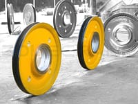
- Walking mechanism using motor, reducer, brake “three in one” combination form, through the dolly centralized drive mode. Bearings in principle using rolling bearings, gears and walking mechanism to go wheel working surface must be surface hardening treatment to meet the specification requirements.
- The lifting mechanism of the trolley and the walking mechanism of the trolley and trolley should be installed with absolute value encoder to provide accurate signal for the electronic control system to indicate its current position.
- The trolley machine room should take measures such as heat insulation, heat preservation, dustproof and rainproof.
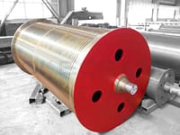
- Lifting mechanism wire rope should be used without distortion, no stress, no loose tendency of 8 strands of steel wire rope, the outer strand surface solid, wear-resistant and lubrication to make the steel core long-lasting rust-free wire rope. Its nominal tensile strength level should be in line with the corresponding current standard products.
- Large car, on, under the trolley walking mechanism are to have broken shaft protector, and easy maintenance.
- Lifting mechanism brake using disc brake.